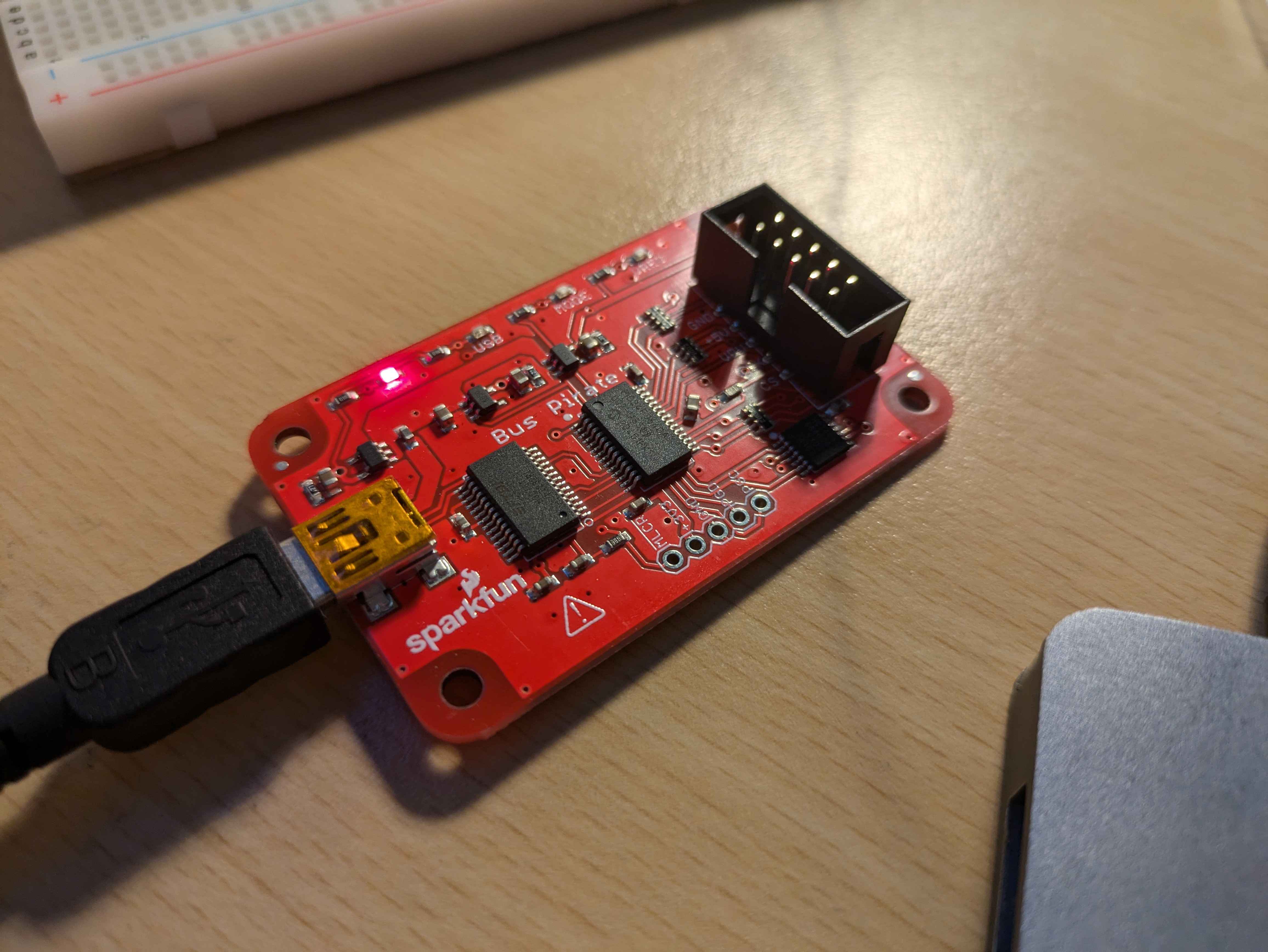
My Bus Pirate V3 (version 5 also exists)
Bus Pirate v3b
Firmware v5.10 (r559)  Bootloader v4.4
*************************************
http://dangerousprototypes.com
*****************
.....
*----------*
Connection
In my case, I’m using Minicom, but there are plenty of other options.
If you’re on Linux, make sure to add your user to the dialout group (or another relevant group depending on your distribution).
Personally, on Arch Linux, I added the user to the uucp group.
(cmd: sudo usermod -a -G [uucp/dialout] $USER).
IMPORTANT: don’t forget to reboot.
minicom -b 115200 -D /dev/tty.usbserial-A10LYGZA
Small script to find the Bus Pirate (can definitely be improved):
#!/bin/bash
echo "Find my bus pirate"
echo "Deconnect pirate bus, and press any key to continue... "
read -n 1 -s -r -p ""
ls /dev/tty* > tmp1.txt
echo "Connect pirate bus, and press any key to continue..."
read -n 1 -s -r -p ""
ls /dev/tty* > tmp2.txt
diff tmp1.txt tmp2.txt
rm tmp1.txt tmp2.txt
#Output exemple
#./find_pirate_bus.sh
#Find my bus pirate
#Deconnect pirate bus, and press any key to continue...
#Connect pirate bus, and press any key to continue...
#3a4
#> /dev/tty.usbserial-A10LYGZA
Self test
To run a self-test, you need to place jumpers between the 3.3V and ADC pins, and between the 5.0V and VPU pins.
Type ~ to start the self-test.
Output:
Disconnect any devices
Connect (Vpu to +5V) and (ADC to +3.3V)
Space to continue
Ctrl
AUX OK
MODE LED OK
PULLUP H OK
PULLUP L OK
VREG OK
ADC and supply
5V(4.95) OK
VPU(4.95) OK
3.3V(3.29) OK
ADC(3.29) OK
Bus high
MOSI OK
CLK OK
MISO OK
CS OK
Bus Hi-Z 0
MOSI OK
CLK OK
MISO OK
CS OK
Bus Hi-Z 1
MOSI OK
CLK OK
MISO OK
CS OK
MODE and VREG LEDs should be on!
Any key to exit
Turning on an LED from the AUX pin
Wiring diagram:
AUX pin of the Bus Pirate → 220 Ohm resistor → LED → GND of the Bus Pirate
To start a connection on the Bus Pirate, type m then 9.
Output:
HiZ>m
1. HiZ
2. 1-WIRE
3. UART
4. I2C
5. SPI
6. 2WIRE
7. 3WIRE
8. LCD
9. DIO
x. exit(without change)

(1)>9
Ready
Using v, A, and a
With v, you can display the state of the different pins (see example).
With A and a, you can turn an LED on or off.
Output:
DIO>A
AUX HIGH
DIO>v
Pinstates:
1.(BR)  2.(RD)  3.(OR)  4.(YW)  5.(GN)  6.(BL)  7.(PU)  8.(GR)  9.(WT)  0.(Blk)
GND     3.3V    5.0V    ADC     VPU     AUX     CLK     MOSI    CS      MISO
P       P       P       I       I       O       I       I       I       I
GND     0.00V   0.00V   0.00V   0.00V   H       L       L       L       L
DIO>a
AUX LOW
DIO>v
Pinstates:
1.(BR)  2.(RD)  3.(OR)  4.(YW)  5.(GN)  6.(BL)  7.(PU)  8.(GR)  9.(WT)  0.(Blk)
GND     3.3V    5.0V    ADC     VPU     AUX     CLK     MOSI    CS      MISO
P       P       P       I       I       O       I       I       I       I
GND     0.00V   0.00V   0.00V   0.00V   L       L       L       L       L
DIO>
On voit bien que la colonne 6 passe H (high) à L (low)
First Program
To return to the default mode, type #. You can enter script mode with s.
To write a new script, type new. Use the command run to execute the script. To list the code lines, use list.
Documentation for BASIC is available here
The following program toggles the LED on the AUX pin on and off every second, about ten times:
10 PRINT "start prog"
20 AUX 0
30 FOR I=1 TO 10
40 LET A=AUX
50 PRINT "LED= ";A
60 IF A=0 THEN AUX 1 ELSE AUX 0
70 DELAY 1000
80 NEXT I
It reminds me of TI-BASIC — good old times. Apparently, high school students now have Python on their calculators!
UART
UART resource: here In this example, we’ll use an Arduino (MKR WiFi 1010). If you have an Uno, check out this lib
Connection:
Bus pirate <-> Arduino
GND        <-> GND
MOSI(TX)   <-> RX
MISO(RX)   <-> TX
Reading from an Arduino (MKR WiFi 1010)
HiZ>m
1. HiZ
2. 1-WIRE
3. UART
4. I2C
5. SPI
6. 2WIRE
7. 3WIRE
8. LCD
9. DIO
x. exit(without change)

(1)>3
Set serial port speed: (bps)
 1. 300
 2. 1200
 3. 2400
 4. 4800
 5. 9600
 6. 19200
 7. 38400
 8. 57600
 9. 115200
10. BRG raw value

(1)>5
Data bits and parity:
 1. 8, NONE *default
 2. 8, EVEN
 3. 8, ODD
 4. 9, NONE
(1)>
Stop bits:
 1. 1 *default
 2. 2
(1)>
Receive polarity:
 1. Idle 1 *default
 2. Idle 0
(1)>
Select output type:
 1. Open drain (H=Hi-Z, L=GND)
 2. Normal (H=3.3V, L=GND)
## ICI choisir 2 //TODO: remettre au propre
(1)>
Ready
UART>(2)
Raw UART input
Any key to exit
azerty
Arduino Program (Uno — note: RX/TX pins may vary)
//Pin TX/RX
//TX 14
//RX 13

void setup() {
  Serial1.begin(9600); //Serial1 = UART communication
  Serial.begin(9600);  //Serial = debugging

  while (!Serial) {
    ;
  }
  Serial.println("Démarrage de la communication série...");
}

void loop() {
  //check user input
  if (Serial.available()) {
    char sendChar = Serial.read();
    Serial1.print(sendChar);
    Serial.print("Envoyé : ");
    Serial.println(sendChar);
  }
}