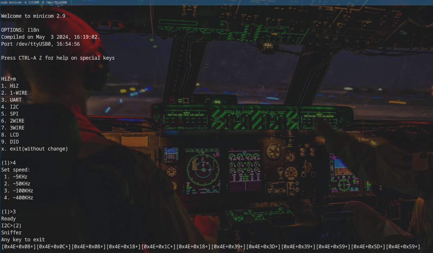
I2C
Sniffing mode
The goal of this article is to use the Bus Pirate to sniff an I2C bus between an Arduino Uno and an I2C LCD screen. Then, we’ll inject values to take control of the LCD screen.
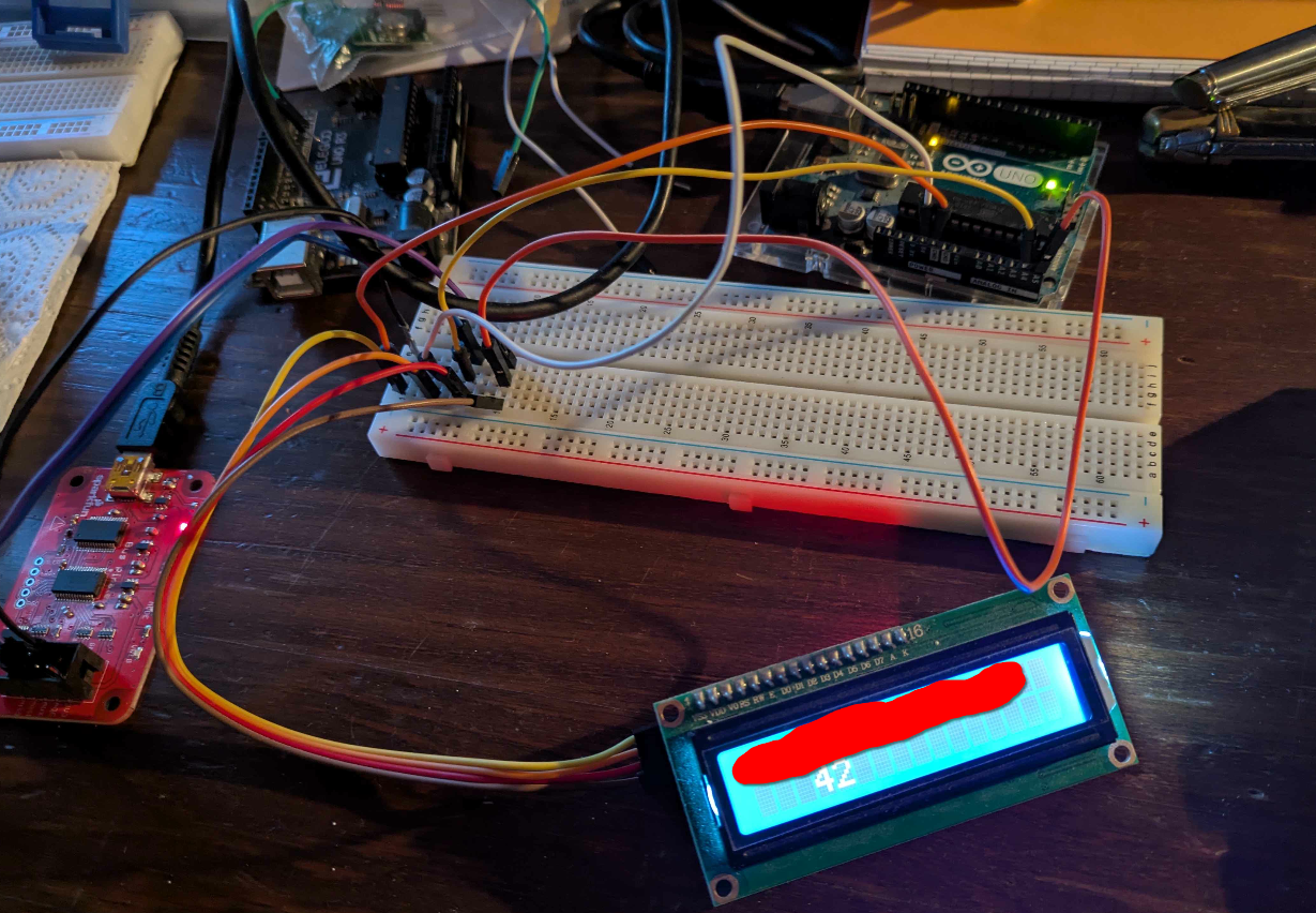
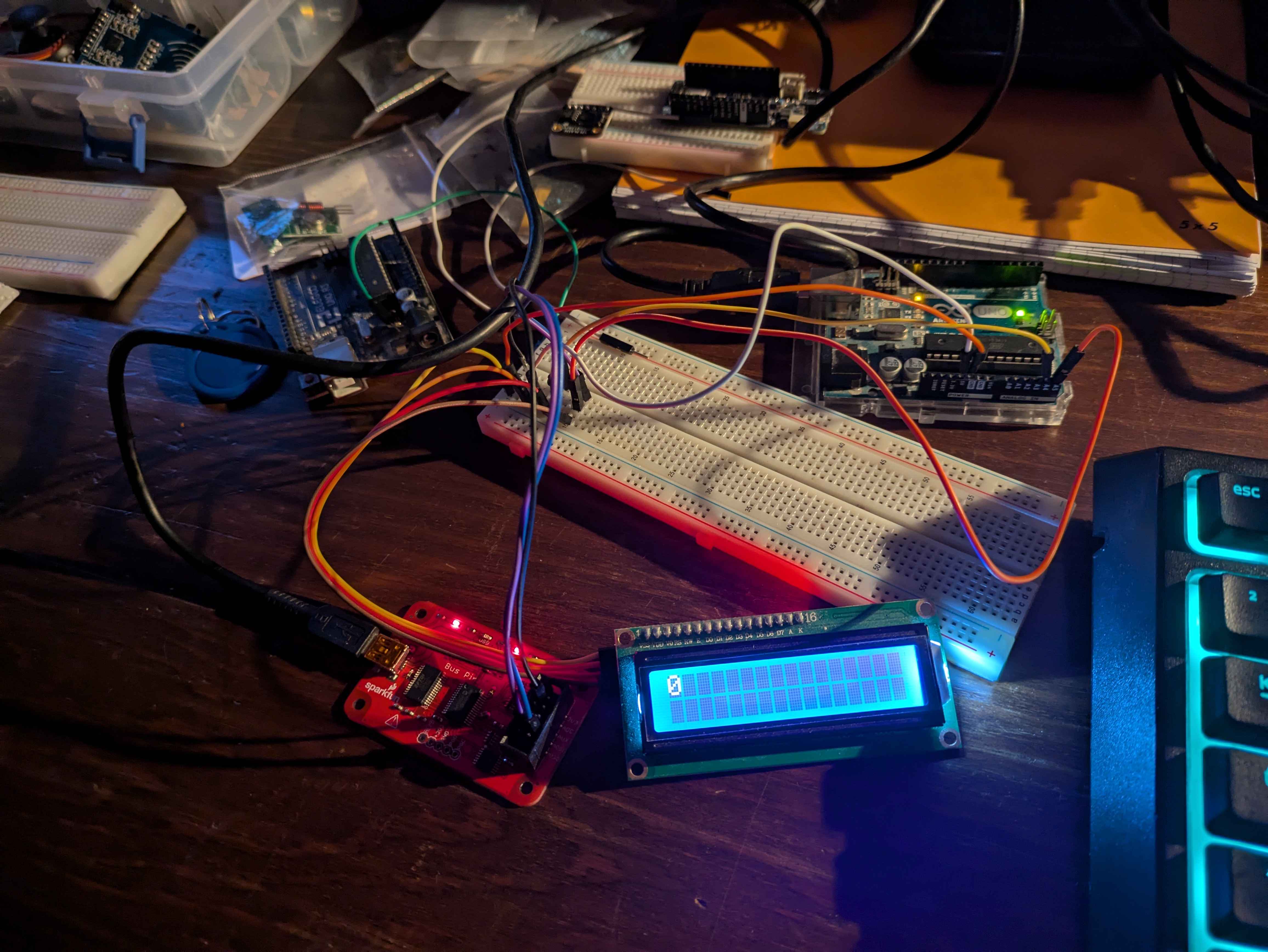
Here’s a photo of the setup:
Steps to sniff an I2C bus:
In this example, we clear the LCD screen and display a number at the cursor position (which is already at (0,0)).
The setup for sniffing is as follows:
Bus pirate <-> LCD screen
GND        <-> GND
MOSi       <-> SDA
CLK        <-> SCL
References for the different protocols supported by the Bus Pirate v3: here
Arduino Code
Arduino code (running on an Arduino Uno):
#include <LiquidCrystal_I2C.h>

LiquidCrystal_I2C lcd(0x27, 16, 2); // I2C address 0x27, 16 column and 2 rows

int c = 0;

void setup()
{
  lcd.init(); // initialize the lcd
  lcd.backlight();
}

void loop()
{
  lcd.clear();                 // clear display
  lcd.setCursor(0, 0);         // move cursor to   (0, 0)
  lcd.print("Hello: ");        // print message at (0, 0)
  lcd.setCursor(2, 1);         // move cursor to   (2, 1)
  lcd.print(c);
  delay(2000);                 // display the above for two seconds
  c++;
  if (c > 10) {
    c = 0;
  }
}
The Arduino/LCD setup is as follows:
Arduino UNO <-> Ecran LCD
GND        <-> GND
A4         <-> SDA
A5         <-> SCL
VCC        <-> VCC
For the reverse engineering, I’ll use the code above.
Reverse engineering
For the captures, I isolated the Arduino code as much as possible to match each line of code with the I2C communication. Also, we have to do it line by line because the Bus Pirate’s buffer is limited.
Capture of clear
Capture for line lcd.clear();
[0x4E+0x08+][0x4E+0x0C+][0x4E+0x08+][0x4E+0x18+][0x4E+0x1C+][0x4E+0x18+]
Capture of setCursor(x, y)
The LCD screen is a 16x2 matrix, with coordinates noted as (column, row).
Capture for the line lcd.setCursor(0, 0);
[0x4E+0x88+][0x4E+0x8C+][0x4E+0x88+][0x4E+0x08+][0x4E+0x0C+][0x4E+0x08+]
Capture for the line lcd.setCursor(1, 0);
[0x4E+0x88+][0x4E+0x8C+][0x4E+0x88+][0x4E+0x18+][0x4E+0x1C+][0x4E+0x18+]
Capture for the line lcd.setCursor(0,1)
[0x4E+0xC8+][0x4E+0xCC+][0x4E+0xC8+][0x4E+0x08+][0x4E+0x0C+][0x4E+0x08+]
Analyse
After several injections from the Bus Pirate to the LCD screen, we can conclude:
setCursor(x,y) To change the value of x, we write to the memory area: [0x4E+0x88+][0x4E+0x8C+][0x4E+0x88+], then send the data: [0x4E+0xp8+][0x4E+0xpC+][0x4E+0xp8+], where p is the value of x, and x ranges from 0x1 to 0xF.
To change the value of y, we write to the memory area: [0x4E+0xC8+][0x4E+0xCC+][0x4E+0xC8+], then send the data: [0x4E+0xp8+][0x4E+0xpC+][0x4E+0xp8+], where p is the value of y, and y ranges from 0x1 to 0xF.
In summary:
setCursor(p, 0): [0x4E+0x88+][0x4E+0x8C+][0x4E+0x88+][0x4E+0xp8+][0x4E+0xpC+][0x4E+0xp8+]
setCursor(0, p): [0x4E+0xC8+][0x4E+0xCC+][0x4E+0xC8+][0x4E+0xp8+][0x4E+0xpC+][0x4E+0xp8+]
Print Capture
For each capture, the screen had to be cleared before displaying anything. So each sequence includes a clear followed by a print.
Capture for the line lcd.print(c); with the cursor at (0,0):
// displaying a 1
[0x4E+0x08+][0x4E+0x0C+][0x4E+0x08+][0x4E+0x18+][0x4E+0x1C+][0x4E+0x18+][0x4E+0x39+][0x4E+0x3D+][0x4E+0x39+][0x4E+0x19+][0x4E+0x1D+][0x4E+0x19+]

// displaying a 6
[0x4E+0x08+][0x4E+0x0C+][0x4E+0x08+][0x4E+0x18+][0x4E+0x1C+][0x4E+0x18+][0x4E+0x39+][0x4E+0x3D+][0x4E+0x39+][0x4E+0x69+][0x4E+0x6D+][0x4E+0x69+]
If we remove the clear command, we get:
// displaying a 1
[0x4E+0x39+][0x4E+0x3D+][0x4E+0x39+][0x4E+0x19+][0x4E+0x1D+][0x4E+0x19+]

// displaying a 6
[0x4E+0x39+][0x4E+0x3D+][0x4E+0x39+][0x4E+0x69+][0x4E+0x6D+][0x4E+0x69+]
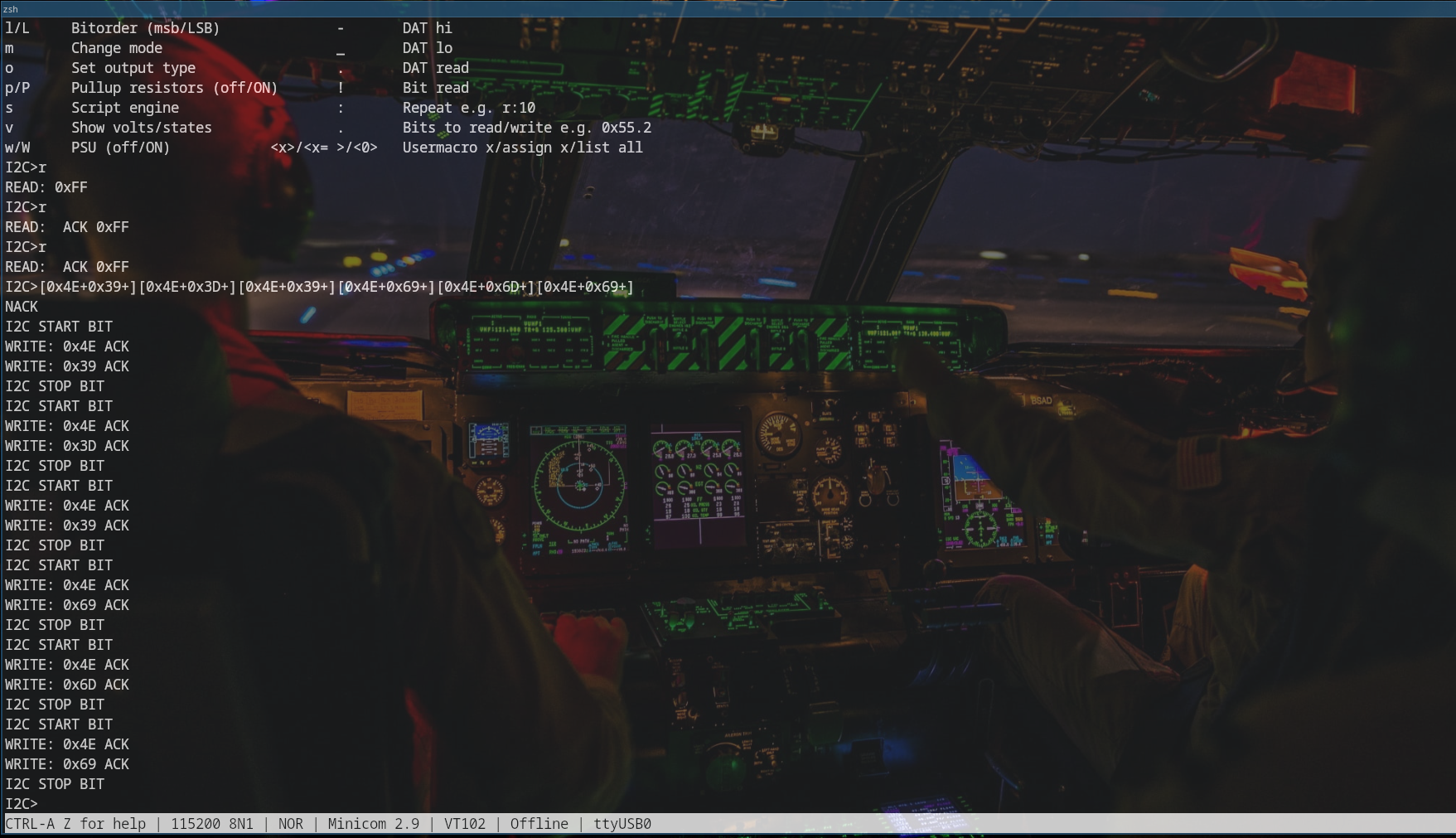
Analysis
Just like with setCursor, a memory area is written before sending the data: [0x4E+0x39+][0x4E+0x3D+][0x4E+0x39+], then a value is sent for display: [0x4E+0xp9+][0x4E+0xpD+][0x4E+0xp9+], where p is the value to display (a digit between 0–9). Note: we’re only analyzing digits here, but the same approach could be used for letters.
Sending a Command
We send a 6 to the LCD screen.
Initial state:
Injection of the digit 6:
Final state:

Ref
Libraries for the I2C LCD screen: here
(Guide to using the LCD screen here)